Back up and running

20170502

Last weekend I fired up the Guzzi for the first time since August 10.  It runs like  champ!  I am still fiddling with the power commander tuning and a few irritating habits it picked up while it was down.  The most annoying is that the shifter doesn’t return to center on an upshift.  If I tap it with my toe it will re-center and work fine, but it makes upshifts really slow.  I have played with the linkage to make sure it isn;t binding.  Next I will have to pull the shifter off the transmission and look inside.

The less irritating one is that the tachometer has gone crazy.  First I had to reset the calibration because it was barely reading anything when I first started.  Somehow the pulse to revolution had gotten set to 2.0 rather than 0.5.  Then even stranger is that under certain very repeatable conditions the tach spikes.  It only happens with full throttle and the engine able to rev up quickly under load.  It won’t do it in neutral from idle, it won’t do it if I use the rear brake against the acceleration and just hold full throttle.  I have two theories, first, I enabled the power commanders acceleration pump feature.  This acts like a carburetor acceleration pump when the throttle if opened quickly.  The accelerator pump wasn’t in the PC the last time I used it so since it si new, and should be responsive to the same conditions that come with the problem I am betting there.  The second theory is a ground problem somewhere.  Given the repeatable nature of the problem the grounding issue may be only a contributor, but grounds should’t care about throttle position.


Reality Bites

20160820

I have been stalled on the RD-400 while I try to solve the rear suspension spacer problem.  My solution is to get a lathe.  I have been saving and searching for a while with no real luck.  Then, last week disaster struck the Guzzi.

The MG V11 have an internal oil filter.  Normally I put a hose clamp around the oil filter as an insurance against it backing off while the engine is running.  Last time I didn’t.  I also didn’t notice that the oil pressure idiot light wasn’t working.  Combine those two last week and I roasted the engine.  It’s ugly.

The rods are not salvagable.  I had to remove one of them with a cutoff wheel because it got so hot the rod bolt welded.

Here is the crankshaft:IMG_1176

This is an excellent picture of a really bad rod journal:IMG_1177

Scored main bearing:IMG_1178

And its matching partner:IMG_1179

And here is where most of the bearing material went:IMG_1180

Fixing this will drain my lathe account…


Let the frustration begin, again.

20160409

What’s next

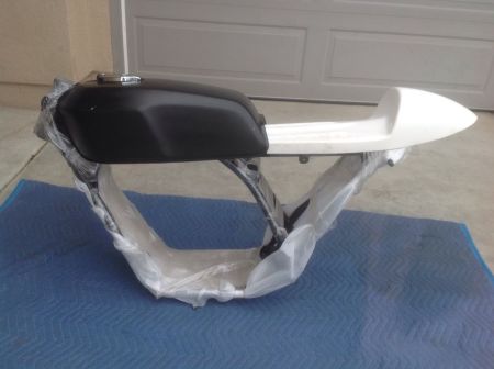
My next project will be a cafe racer based on a 1976 Yamaha RD-400.

I found a basket case (literally, it came in baskets!) RD400 on eBay.  I have wnated to do something like this for a long time: a tiny, light cafe.  I have never had a two-stroke and the RDs had great reputations.  I have always wanted an RZ350 but those are getting collectible and I don’t do that…

RD400 01.jpg

Fantasy garage

The initial set of parts did not include wheels or a swing arm.  This was good, it made it easier to decide to go all out and make this really different.  I started off with a few ground rules: I wanted modern tires, but not enormous tires the bike couldn’t deal with and I wanted to keep the suspension geometry as close to “as designed” as I could. I will also not take short cuts on this build.  I have no deadlines and will take my time and do what I want here

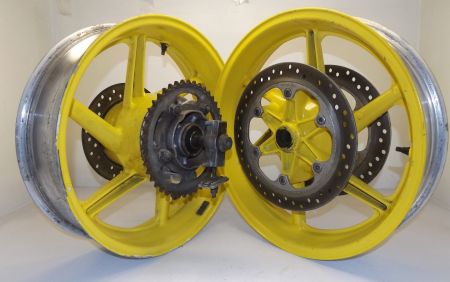
The original RD400 came with 18″ wheels which are evidently enormously heavy and very narrow.  18″ tires are getting hard to find so I set about looking for a set of 17″ wheels that could take the sorts of tires I wanted.  I am targeting 110/70R17 and 150/60R17.  Both of these sizes are easy to find with modern radial construction.

Ninja 250’s were my first bet.  It is a light low powered bike built continuously sine the 80s.  But as it turned out until very recently (2008) it had 16″ wheels.  That left only very recent bikes and finding wheels was difficult.  I started looking at early 90’s sport bikes and found the the CBR600 F2 had the size tires I was targeting.  And wheels were pretty easy to come by.  There are other bikes that could lend their wheels, FZ400s wheels are popular swaps, but

I don’t really like the three spoke designs so common today.  The CBR wheels are six spoke and look good (they will not be yellow when I am through!).

68BBBFE8-1E09-4A8D-832D-9A7B2655B3B1

Researching the RD400 on various forums indicated that late 2000’s GSXR-600 forks were a good fit to move up from the spindly little forks the bike came with, and they are pretty cheap to come by as well.  The All Balls Racing website has an excellent search function for doing fork swaps.  They showed that to put these forks on the RD400 frame I would need 30mmx48mm Roller Bearings.

So, here I had an RD400 frame, CBR600F2 wheels on the way and GSX-R600 forks.  Now I could sit and wait for the part to arrive.  And the bike is taking shape in my mind and perfection is mine for the taking!

Reality Garage

Rotors

Mixing and matching parts from various manufacturers is not for the faint of heart.  For example, the GSXR forks are set up for 310mm rotors, but the CBR600 wheels are 298.  The bolt pattern for the wheels is 6x166mm which is very unusual.  I found a parts list for EBC brakes that showed the modern Triumph Thruxton had the same rotor bolt pattern so I order some of those rotors.

Front wheel bearings

My research show the CBR wheels use 47mm bearings with a 20mm axle.  The GSXR forks are set up for a 25mm axle so i bet on the come and ordered so 25mmx47mm bearings. And here was my first dose of reality:  The CBR wheels actually had 42mm bearings.  OK, that isn’t tragic and I found some bearings that should do the trick, they won’t last 50,000 miles but they should do.  Of course I had to order them.

Fork Swap

The bearing from All Balls Racing showed up and worked quite well, except that I mis-measured the length of the fork stem and pressed the lower bearing in without any spacers.  I almost had the new back bearing back off when my tool slipped and irreparably damaged the race.  So I cut that one off and pressed in the other new one on with spacers to make up for the longer stem and ordered yet another bearing from All Balls.

Sprocket Trouble on the Horizon

For giggles I put the CBR rear wheel in place in the RD frame with the wheel centered. It looks very much like I am going to have to play serious games with the sprocket carrier to get the chain to clear the frame.  Oh, and if I wanted anything like the original wheel base I will have to build my own swingarm.  Well, I am doing this for the challenge.

So begins another project where it will likely be 2 steps forward and one step back for a long, long time.

Today’s scorecard:

Fitting Thruxton rotors to the CBR front wheel Win Research worked, rotors fit perfectly and the rotor bolts even fit.
Fitting the GSX-R forks to the RD Frame Tie Will ultimately work, but I lost style points for mis-measuring and destroying a brand new bearing
Fitting the CBR wheel to the GSXR fork In play Found bad data and ordered the wrong bearings, but there is plenty of room in the wheel for the bigger axle once the correct bearings arrive.

V11 Sport with Laverda Fairing

20151030

IMG_0972 IMG_0978 IMG_0977 IMG_0976 IMG_0975 IMG_0974 IMG_0973


The M3 Today

20140313

DSCF3638

DSCF3637

DSCF3636

DSCF3635

DSCF3634

DSCF3633

DSCF3632

DSCF3631

DSCF3630

DSCF3629

DSCF3628

DSCF3627

DSCF3626

DSCF3625

DSCF3624

DSCF3623

DSCF3622

DSCF3621

DSCF3620

DSCF3619

DSCF3618

DSCF3617

DSCF3616

DSCF3615

DSCF3614

DSCF3613
DSCF3612


Preparing to build Space Derby Kits

20121005

The Space Derby is just around the corner.  If you would like to build the kits during your meetings with the kids, there are a few things you can do to make it much smoother and more enjoyable for everyone.  These are tasks that either take too long, or are too difficult for the little kids to do.

Preparing the Bodies

The first thing to do is to join the two halves of the body together. This is very simple, but the glue can take a while to dry enough for the kids to start in with shaping the bodies. Use a thin coat of any wood glue (Elmer’s school glue is fine) and put the two halves together. Make sure the holes on each end are the same size. You will have something like this:

Once the body is dried you need to cut notches in the back of the body so the rubber band has something to grip. Look at the body, and on the end with the LARGER hole cut two notches as in this video:

Building the Propeller Assemblies

Now you need to assemble the propellers. This is a bit fiddly, and requires more strength and coordination than the younger are likely to have. First you need to adjust the propeller shaft. As it comes from the Scout the opening is too small to get the rubber bands in:

Use needle nosed pliers to open up the end so the rubber band can go in easily:

The rest is pretty straightforward, but difficult to explain in words, so here is a short video:

The rest of the instructions are pretty good and the kids should be able to do the rest pretty quickly.


The M3

20120610

This has been my current project since last August.  Lots of electrical reconditioning, soon I will get to the driveline.  Garden variety Cosmos Black 95 M3.  First year of the finest M3s made!

ImageImageImageImageImage


BMW E36 Air Conditioning Relays

20120524

All relays are not equal. Especially in a BMW. The pin layout is standardized, but the electrical function of the pins can be different from application to application.

In my case the previous owner apparently didn’t get this and just got three cheap relays from Pelican (BMW Part # 61.36-1 391 397, these are gray) and stuck them in when he restored the AC system after removing it for AutoX duty. He was two-thirds lucky.

Using that relay on the high speed fan caused big problems:

The burnt out connector is for the high speed fan relay. By using the wrong relay, the interlock that prevents the high speed and low speed winding from being turned on at the same time was defeated and the 30AMP fuse 41 was fed directly through the small gauge wiring feeding the relay control. So it burned up.

This connector was shot, I could not remove the burnt in pins and had to cut the connector out and splice a new one in.

For future trouble shooting and clarification, here is a diagram that details what relays go where, and what the pin functions are (this appears to hold for every year of M3, and may hold for all E36, YMMV, caveat emptor, don’t sue me etc. etc.):

The proper relays are

  • High speed fan BMW #61.36-1 391 397
  • Fan Clutch Relay BMW #61.36-1 389 105
  • Low speed fan relay BMW #61.36-1 389 105

Many thanks to Todd at the M3 forum for taking the time to give me the part numbers for the relays that were installed in his car.


Finding Shorts on a distributed circuit.

20120420

For the last few months the instrument lights in the M3 have been flickering when I hit bumps. Eventually they completely failed. This is how I found the fault:

I assume basic electrical knowledge, which means you have a meter that can read resistance and voltage and that you understand what “continuity” and “shorts” are.

The first resource is the Electrical Trouble Shooting Manual (ETM in the vernacular, grab one for your BMW) Schematics 6300.0-00 through 6300.0-02 show the interior illumination circuitry.


When you look at the schematic for the instrument lights (6300.00) you see they are fed from the headlight switch into junction X196 to the dimmer switch into junction X1019 and out to all the lights (grey/red wires). At first I though I had an open circuit since I had no blown fuzes. Since EVERY light went out at the same time that narrowed it down to a few possibilities:

  1. the headlight switch failed
  2. the connection from the headlight switch to the dimmer failed
  3. the dimmer switch failed
  4. the supply from the dimmer to the splice had opened.

My money was on the dimmer switch since even before the lights failed I had to jimmy the dimmer to get the lights to come up to full brightness, it acted light a rheostat with a dead spot.

I pulled the dimmer switch and headlight switch and checked continuity in the wires, all was fine. The headlight switch had some small pieces rattling around inside, which was not a good sign. The switch continuities checked out, but I ordered a new switched anyway. I disassembled the old switch and found that 18 years of temperature cycles had turned the plastic detent ring inside the switch into a thousand pieces of brittle plastic. I still had hopes that the dimmer switch was too blame and I had no way of directly testing it. When the new switches arrived, I changed them out. Nothing, the problem was still there.

I had all the signs of an open (shorts generally blow fuses) but wire continuities all checked out. This was very confusing until John Firestone on the M3Forum clued me in that the dimmer switch has built in short circuit protection. So, my assumption that a short would blow fuses was wrong. I checked the output wire from the dimmer switch (grey/red) and sure enough it was shorted.

There are 22 individual wires shown in the schematic that could be shorted to the chassis (all the wires from junctions X1019 and X13129). These wires spread completely throughout the car and include two splice junctions. Since they are all spliced together a short on any one of them shows up on every other wire as if it were on that wire. Find a chafing wire by doing a hand over hand search would take weeks and pulling most of the interior out of the car. I needed to more narrowly isolate the fault. The junctions shown in the schematic (X1019 and X13129) are the keys to isolating the ground. In my car there is no junction X13129 since it is a coupe. That left me with junction X1019.

The idea is to get to the splice junction and disconnect all of the wires from the junction. Then you can check each individual wire for short to ground. That narrows the problem down significantly.

Sounds great, except that getting to the junction box is a MAJOR undertaking. Many thanks to John Firestone for pointing me to Jeremy Reyna’s Power Vent DIY which had some critical information.

  1. This requires removal of the drivers seat unless you have no spine.
  2. remove the drivers kick panel and under dashboard panel. The splice box is cliped to the outboard sheet metal above and outboard of the clutch pedal.
  3. First, you have to remove the check control module. Since it is directly above the splice panel it seems like you should pull the splice panel first. There is no clearance to do it in that order. The check control module is held on by two plastic nuts that can be removed using your fingers. The forward nut cannot be seen from beneath the dash, you have to go by feel. Once the nuts are removed you can work the CCM out from above the splice panel.
  4. Now the the CCM is out of the way you can reach above the splice panel and feel a locking tab that is on the top outboard side. With one hand above you can pull the tab, with the other hand you can push up and the splice panel will release.

* Installation is in reverse except you can put the far CCM nut on first since the CCM has a slot instead of a hole. But you must put the splice panel in before the CCM.

Once the the splice panel is accessible you can pop out the splice for the red/grey wires and start pulling the wire off of the fan connector. This is NOT easy, and I had to use needle nose pliers. It is easy to break wires, so think through how to do this in the constrained space.

Once the wires are all free check grounds on all of them. If you are luck you will have only one ground. You can hook the rest back up and recover most of your lighting, then you can hand-over-hand inspect the faulty wire.

In the end I had a very small short caused by chafing on the wire leading to the DC power receptacle light.


Guzzi “Roper” Plate

20120420

I finally got around to installing my Roper plate this morning.  So easy I didn’t bother to take pictures.  For reference there is a very good writeup at V11LeMans.com.

Since I had the sump apart I was able to inspect the bottom end and everything looked very clean.  The post instlal test ride showed that I no longer get oil pressure lights under heavy acceleration.  Mission accomplished!