Brake Hydraulic Theory
Most people will be be starting with a brake caliper from a particular car. The goal is to find out what size master cylinder should be used to give acceptable pedal force, and also to figure out how to proportion the braking forces between the front and rear wheels. Before we jump into that let’s look at brake system basics.
Basic Hydraulics
The fundamental concept behind hydraulics is the incompressible fluid. A fluid is a material that can flow into any volume. Gases and liquids are all fluids, the principle difference being the amount of compressibility they exhibit. The other unique characteristic that all fluids share is that the pressure is the same everywhere within the fluid region (neglect the effects of gravity, it doesn’t play on the size scales we are talking about). For example, let’s fill a 55 gallon drum completely with water, so that there is no air in the tank. If I push on the bottom of the tank the top of the tank will start to bulge (so will the sides, but not as much since they are thicker material). The force on the bottom of the tank got transmitted to every part of the tank. Now let’s get another 55 gallon drum and completely fill it with water as well. Connect it to the first tank with a hose, and get rid of all the air from the system. Again if I push on the bottom (or the top) of the first tank, the force will be felt every within the fluid, even the second tank that we just connected. Now we are starting to see our hydraulic system, the drums are the master and slave cylinders and the hose is, well, the hose.
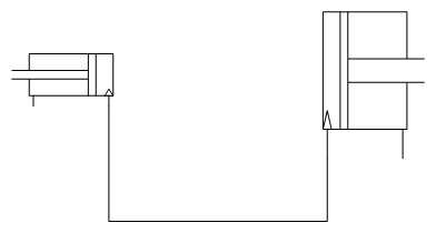
This is our first hydraulic system. On the left is our master cylinder, on the right our slave cylinder. The key to remember is that the hydraulic fluid is incompressible. It will always have the same volume no matter what we do. If we move the master cylinder piston, then the volume inside the master cylinder changes, the volume of the rest of the system has to change in order to keep the total volume constant. Assuming that the hydraulic lines are perfect and never change the volume change in the master cylinder is going to have to be matched by a volume change in the slave cylinder.
The volume change in the master cylinder is

Where 


OK, but what about pressure? That’s easy, the pressure is the same everywhere. And we find it by dividing the force on the master cylinder piston by the master cylinder area:

Now what is the force exerted by the slave cylinder piston? We know the pressure in the slave cylinder, it is the same as in the master cylinder. The force on the slave cylinder piston is the pressure times the area of the slave cylinder:

So now we have the entire picture. If the slave cylinder is bigger (in diameter, and therefore area) than the master cylinder we get a bigger force out of the slave than we put into the master, but a smaller movement. Just like a lever.
Automotive Brake Systems
The hydraulic system is simply a means to and end. We want to actuate a control and have the car slow down. In our case that means push on a pedal with our foot and have the car slow down.
The Master Cylinder
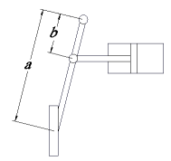
Our ideal hydraulic system is a pretty good model, but we need to add some things to it to make it applicable to automotive systems. The first addition is to the master cylinder. We do not act directly on the master cylinder piston, but rather, through a brake pedal that adds mechanical advantage. If we apply a force on the brake pedal we get a higher force on the master cylinder:


If we press on the pedal with 70lbf and the pedal ratio is 7, then the
force on the piston is 490lbf.
The Wheels and Rotors
Now that we can get the hydraulic system up to pressure how do we use that to slow the car down? Most modern cars use disk brakes in the front and while most use disks in the rear now as well, there are many (including most trucks) that still use drum rear brakes. The Locost Calculator assume four wheel disks and that is what we will talk about here.
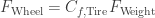
All modern disk brakes systems rely on brake pads pressing on both sides of a brake rotor to increase the rolling resistance and slow the car down. The amount of frictional force is found by multiply the force pushing the pad into the rotor by the coefficient of friction of the pad.
The next place to review our model is to look at the business end of the braking system: the calipers. There are two types of calipers in broad use today: floating calipers, and fixed calipers. Racing cars use multi piston fixed calipers while the vast majority of production cars use floating calipers. Floating calipers have a piston (or pistons) acting on one side of the disk to press the brake pads into contact with the brake rotor. As the pistons push in the entire caliper slides on pins to center the brake rotor between the pads. Fixed calipers have pistons on both sides of the rotor and keep the caliper fixed in place when the pistons act. The advantage is that the caliper can be smaller and allow a larger rotor inside the same wheel. They also flex far less than floating designs.
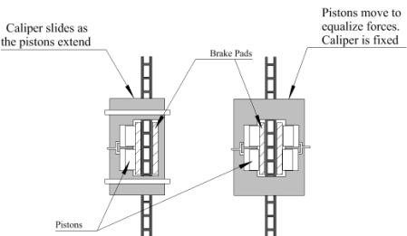
The diagram above shows the two types of caliper, floating on the left, and fixed on the right. To find out how much force the pads are getting find the total piston area ON ONE SIDE of the caliper. For a floating caliper that is just the total piston area. For a fixed caliper use only the inboard or outboard pistons. Then use that force on both brake pads.
Why pressure from only one side?
This can be a little confusing and some very smart people have gotten caught. But it really isn’t that hard to understand if we shift our thinking a bit. First, ignore whether or not the caliper is fixed or floating; it doesn’t matter, and in a minute you’ll see why.
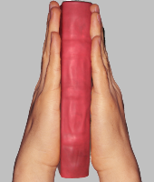
Imagine that you are holding a book between your two open hands. Now squeeze on the book. If your left hand is pushing with 25 pounds of force, then your right hand has to push back with that much force or the book will move across your chest. Each of your hands is a brake pad, and the book is the rotor. The force between the pad and the rotor is only 25 pounds, not 50. And it is the force between pad and rotor that determines the frictional force generated on the brake rotor.
In this respect there is no difference between floating and fixed calipers. The other side just acts to keep the rotor centered in the caliper, one moves the whole caliper, the other moves the other pistons.
But wait! There are still two pads, one on each side. If we replace one pad with a ball bearing surface the force on the rotor from the brake caliper would be reduce about half. So we have to count both pads, but using the force generated by one side of the pistons.
So, the force slowing the brake rotor is

But the force that slows the car down is really the force the wheel exerts on the hub, which is the same as the force the tire exerts on the road (ever action has an equal and opposite reaction). But how do we turn the slowing force on the rotor into the force the tire puts on the road? By turning it into a torque, because the torque on the rotor from the pad is the same as the torque on the tire from the road. The torque the brake pad puts on the wheel/rotor is the force on the rotor, given above, multiplied by the radius the force acts on, which is essential at the center of the pad. For us, we take the brake disc radius (diameter divided by two) and subtract half of the slave piston diameter (which assume the pad is centered over the piston, which is a good assumption in general):

Since we now know the torque on the wheel we can find the force of the road on the wheel, which is the force on that tire slowing the car down,

But wait, there’s more!
Center of Mass, Wheelbase and Weight Transfer
The car has four places that are exerting forces to slow down the car. We treat the two front tires as identical, and the two rear tires as identical. When we talked about brake pads we said that the frictional force they generated was proportional to the force pushing them into the brake disc. The same holds for the tires, the force generated by the tires to slow down the car is the force pushing the tire into the ground multiplied by the tires coefficient of friction.
Static and Dynamic Friction
Friction is a tricky beast, and in a very real sense no one on earth really understands it. But we can describe it a bit by coming up with some magic numbers called coefficients of friction. There are two types of friction: static and dynamic. Static friction is what keeps something from sliding, dynamic friction is what slows it down once it has started sliding. For an example, place your hands flat together (like above, but without a book between them this time) and press them together. Now that they are pressed together try to slide them across each other, without releasing the pressure you are applying. You will find that at first they don’t move but after you build up enough force they “break away” and slide very easily. Before they started sliding you were trying to overcome hat static friction, once they started sliding the dynamic friction was what you felt as they came apart. For all materials you will run across in your daily life (unless you work in a cryogenics lab) the static friction is higher than the dynamic friction. That is what is meant by “the limits of adhesion” when you hear about race driving. Keeping the tires generating as much force as possible without letting the start to slide is the most effective use of the tire. You may also hear about static friction when people talk about “stiction” in coilover and dampers.
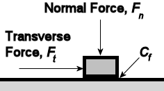
There are two forces we are concerned with in friction. The first is what engineers and mathematicians refer to as the “normal” force, this is the force acting perpendicular to the surface we are trying to move the block against. The second force is the transverse force, this is the force trying to move the block over the surface… So since we really don’t understand friction, we measure the coefficients of friction between two materials and report those numbers. The coefficient of static friction tells you how much transverse force you can apply before the things start to slide. If is what we are concerned about where the tires touch the road. The dynamic coefficient of friction tells you how hard you have to push to keep the thing moving, or how much force will slow it down if you do nothing. The dynamic coefficient is what we are concerned with at the brake rotor and nearly everyplace else that we ever talk about in a car.
So if we are trying to design our brake system to let us decelerate a certain amount we design as if we were braking with the tires right at the limit of adhesion, or just before the tires start to slide.
The problem is that the weight on the tire changes after we start braking. Since the center of mass of the car is above where the force on the tire is slowing the car the weight is shifted forward. But how much?
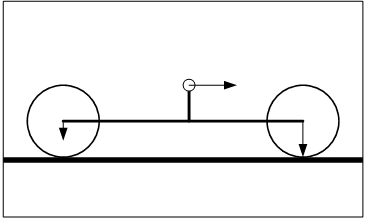
To figure that out we need to know few things, first, how high is the center of mass of the car above the ground? Second, how much of the weight of the car is on the front tires when the car is as rest (which is really just another way of know where along the length of the car the center of mass is). Third, how far apart are the wheels, or what is the wheelbase? And lastly, what is the weight of the car?
If the car is moving at a constant speed, then a certain percentage of the cars weight is on the front wheel, and the rest is on the back wheels. When the car starts to slow down, some weight gets added to the front wheels, and the same amount of weight gets removed from the rear. This is what causes cars to dive under braking. To find how much weight is transferred think of the car as if it were a crank with its handle on the CG. The braking force tries to make the car dive, and the front wheels try to keep it level. The torque on the crank from braking is

The torque trying to keep the car from diving is

where WF is the percentage of weight on the front wheels and 


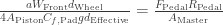
Which give the amount of force added to the front wheels when the car is braking. So the weight on the front and rear wheels under braking is


Slowing the Wheels
Now that we have the weight on each of the tires we can find how much braking torque needs to be applied to get a certain level of deceleration. Assuming that we are at the limit of the tires, but not locking up, the force acting to slow the car down from one of the front wheels is:

But that still leaves a pesky friction coefficient for the tires. We can get rid of that if we remember that we are decelerating the entire car at rate, a. That means the sum of the braking forces from the front tires and the rear tires must be ma, where m is the mass of the car.


But,

So,

Which means,

Remember from above we already have one way to find the road force on the tire:
So now we have a way to start with the desired deceleration of the car and work our way to the master cylinder size.

Now, transform the wheel torque into the force on the rotor


Moving the Calipers
From the force slowing the rotor we can find the force on the brake pads. The force on the rotor is divided evenly between the two brake pads, so the force on the brake pad from the piston is

Now we find the pressure required to generate that piston force,

That pressure is generated by the force on the master cylinder. The force on the master cylinder is the pedal force multiplied by the pedal ratio. So,

Since the pressure at the master cylinder is the same as the pressure at the pad piston,
Now, solving for the area of the master cylinder,

If you use more than one master cylinder, the force on the pedal needs to be divided equally between the front and rear master cylinder. If you use a bias bar, it should be adjusted as close to even as possible and only taken away from equal bias to adjust the system once everything is installed.

Hi,
IMO, this is an excellent monograph, although simple stuff for a mathematician……I find the equations slightly confusing for a non-mathematician and hard to follow without constant review…….otherwise it would be a piece of cake.
If an example calc was used after each equation and/or explanation, I think most everyone could follow along without a problem.
Thanks man!
John
Thanks I hope it helps you understand braking systems. If I have some time I’ll do an example calculation. You can be a character witness at my trial when some nutcase decides to use my exact calculation for his Locost and plows into a busload of schoolchildren!
Craig
Hi Craig,
Absolutely, an extremely helpful piece with great physical examples.
Hmmm, never thought of that, but in any case, you got it!
Thanks!
John
You forgot to mention that on fixed brake calipers, multiple pistons are often used to apply a greater amount of pressure to the brake pads than just the standard pair of pressure points in many designs.
By using the principals of fluid dynamics, you can multiply the clamping force of the calipers pistons by increasing fluid transfer to a greater number of caliper pistons at once and or a larger diameter of pistons, and without any added initial force from the driver other than having to increase the distance of their foot travel.
By doing this, overall stopping force is increased.
Source: http://www.cquence.net/blog/how-caliper-clamping-force-varies-between-designs/
Of course you are correct. I try to keep this a bit simple. I also don’t discuss the effects of hydraulic line expansion, caliper twist under load and all the other factors that a real design would have to incorporate.
In any event, in the case of a multiple piston design you can use these calculation by assuming one piston with area equal to the multiple pistons.
Hello i am a non engineer amateur who wants to learn and just wanted to ask, how do you figure the equation for this, do you come with your own based on analysis or is there references for that?
i went through a lot of references just for brakes and didn’t find anything for caliper twist for example.
so if you have books or you come with your own please do tell me how.
Thanks
If you go from 17″ wheels to 20″ wheels that have larger radius tires, does that reduce the effectiveness of the brakes? The tire patch on road now has a larger lever arm to which resist the torque of the brakes. I ask because I feel like my braking performance is reduced with larger wheels and tires on my truck.
Yes. There are a a few contributing factors. First is the larger lever arm as you mentioned, the second is that the larger wheels usually weigher more and concentrate their mass further out form the center, this increases the rotational inertia of the wheel by quite a bit. I do not address inertia from the wheels in this explanation. As a general rule larger wheels are no good for performance.
Thanks, enderw88. I’ve loaded an acceleration app on my tablet and began testing g-forces generated by the braking system this morning. Subjectively, the braking performance with 17-inch wheels feels more than with the 20-inch wheels. I’m going to see if I can measure objective data also.
Let me know what you find. Data is always good.
@enderw88
i want to know the reactions forces which acts on the rear and front wheel of the tyre.
Not sure how to answer this, but you can consider the car as really only moving in two dimensions. The contact patches can see a load in pretty much any direction in the horizontal plane when you consider all conditions of turning, accelerating or braking.
I find these confusing, but I appreciate that you took the time to explain them. I use these guys for my metals, if that helps. Just a small contribution. Thanks for the help!
I want to know how the equation T upright = Ffront (1-WF/100)/Lwb comes from
It is a simple torque equation. Torque=force times distance. the force is on the front wheels, the distance is the proportion of the wheel base.
Shouldn’t it be Tupright = Ffront*(1-WF/100)*Lwb at least?
However, I do not understand the (1-WF/100) factor, and this website http://www.engineeringinspiration.co.uk/brakecalcs.html seems to disagree. Lastly, I think you have inconsistencies using WF as a percentage and as a fraction.
Otherwise, very helpful. Thanks for putting it all together in plain English.
@Hunter,
Three things: first the (1-WF/100) * Lwb is the distance from the center of mass to the front wheel. second, you are correct that I inconsistently use WF, third you are correct that is should be * Lwb. How I missed that for the SEVEN years since I wrote this page I will never know. THANK YOU!!!. I guess you are the first person that actually READ the page. It has been corrected.
I don’t see the disagreement with the page you pointed to.
Is int the pressure at the master cyclinder equal to the ( Pedal force x pedal ratio ) DIVIDED BY (area of master cyclinder ) @ “Moving the calipers” section
Wow! How did I miss that for all these years…yes you are correct. I have fixed it.
In your basic hydraulics section, am I correct in saying that P = F “divided” by A, rather than “times”, which is what you have posted? I apologize if I am wrong.
Of course you are correct, the words were right but I had a typo in the formula. Thank you, I have corrected it.
In a pedal box situation ie with dual master cylinders, am I correct in saying the pedal force multiplied by mechanical advantage (call it 400lbf) will be distributed across both master cylinders in a ratio according to the differing master cylinder diameters (assuming they are different)? Or does each master cylinder have 400lbf acting on it?
Question about brake system theory:
If enough force was applied to a master cylinder piston to produce 100,000 PSI in the brake fluid And the diameter of this piston is 3 feet
(Dia. 3’ = 36”__Radius = 18”___Area = 3.14*18*18 = 1018 in-sq)
And If the pressurized brake lines then apply pressure to multiple slave piston, and the diameter of these slave pistons is .25 inches
(Dia. = .25” Radius = .125”___Area = 3.14*.125*.125 = .05 in-sq)
Since 1018 in-sq /. 05 in-sq = 20,360
Then, is it theoretically possible for 100,000 PSI to be simultaneously applied to 20,360 slave pistons when a 3 foot diameter master cylinder piston applies 100,000 psi to the brake fluid?